
How the Design of the TPE331 Contributes
to the Engine’s Efficiency

By Helmuth Eggeling
The TPE331 engine that powers all turboprop Twin Commanders has been around for decades, but the operating principles that guided its design�simplicity, power, fuel efficiency, and safety�are as relevant today as when the first production engine appeared more than 45 years ago. The following article, which is adapted from Honeywell�s TPE331 Pilot Tips booklet (available online at https://www.e-engines.honeywell.com/index.jsp; point to �Communications,� then �Pilot Information� then click on �Pilot Tips Book�) takes a look at the design and operation of the engine.
The type (model) selection of an aircraft engine is often influenced by the high cost of fuel. At low to medium airspeed (about 375 mph/325 kts), turbine-powered propellers produce thrust more efficiently than any other propulsion system.
TPE331 DESIGN
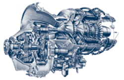
The TPE331, a lightweight single-shaft turboprop engine, meets the market demands for efficient and compact turboprop engines. Like the reciprocating engine, immediate propeller thrust is available with the added bonus of jet thrust due to the flow-through design.
Operational Principle
The TPE331 is a torque-producing engine. It extracts power by converting heat energy into rotating mechanical energy (torque). Ambient air is drawn in and compressed by a two-stage centrifugal compressor. Exiting the 2nd stage diffuser, air is directed into the annular combustion chamber and mixed with fuel. The fuel/air mixture is ignited and a continuous combustion is maintained. The expanding gases enter the turbine nozzle area, experiencing further flow acceleration due to the convergent turbine nozzle design. Nozzle-directed airflow impinges upon the first-stage turbine rotor, causing it to rotate. The hot gases continue their flow through the remaining nozzles and turbine rotors, and finally back to the atmosphere as exhaust.
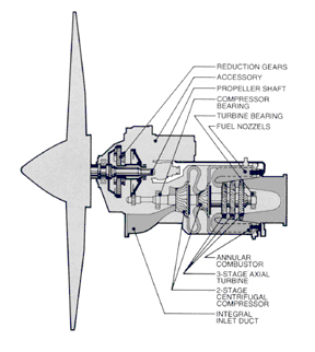
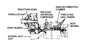
TPE331 Engine Components
Rotational turbine motion is transmitted to the compressor section and the gearbox through a common fixed shaft. Approximately two-thirds of the mechanical shaft power produced by the gas generator (the compressor, combustor, and turbine section) is used to rotate (drive) the compressor. The gearbox converts the remaining high speed/low torque energy into low speed/high torque energy needed to drive the propeller and engine accessories.
Certification Considerations
The TPE331 design provides the safety features and design specifications for transport category aircraft certification requirements of Title 14 CFR Part 25. This includes Negative Torque Sensing (NTS) to automatically decrease propeller drag in the event of fuel starvation or engine shutdown.
Maintainability
Design simplicity provides for low periodic maintenance costs of the entire line of TPE331 engines. With only one main rotating assembly, extended operational periods between overhaul have been realized. TBOs as high as 9000 hours have been approved on engines in airline operations, and a mean time between in-flight shut down of more than 63,000 hours has been attained.
Dynamic balance of individual rotating elements prior to final assembly results in smooth, vibration-free operation and allows �in-the-field� replacement of individual rotating components.
Superior Installed Performance
Rated performance of an uninstalled engine is only part of the TPE331 performance story. What really counts is engine horsepower when installed in the airframe. The high propulsion efficiency obtained from the �front-to-rear-flow� TPE design also provides some exhaust jet thrust and one of the highest ram pressure recovery in this turboprop engine class. Low frontal areas and compact dimensions reduce installation drag to a minimum.
Environmental
The annular reverse-flow combustor of the TPE331 essentially eliminates visible smoke emission. With axial fuel injection, compressor air swirl provides a more homogeneous fuel-air mixture in the primary zone and minimizes oxygen-deficient areas, resulting in a clean-burning, fuel-efficient engine.
Advantages of Design Features
Centrifugal Compressor:
The two-stage centrifugal compressor converts mechanical energy into pneumatic energy.
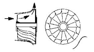
[centrifugal compression airflow pattern illustration]
Compression Ration:
Higher pressure rise per stage associated with a better compression efficiency over a wide rotational speed range (from idle to full power) clearly characterize the important advantages of the Centrifugal Compressor as compared to an axial-flow type compressor. (Axial compressors often require automatic air bleed to eliminate compressor stall during acceleration from low engine speeds.) For example, the TPE331 requires only two compressor stages to achieve up to 11.4:1 compression ratio with a total air mass flow of up to approximately 12 pounds per second at sea level on a standard day.
F.O.D. Resistance:
Unlike axial flow compressors used in similar power-class turboprop engines, the TPE331 has been proven to be highly resistant to F.O.D. without inlet screens and/or foreign objects separator ducts. (Engine designs that require inertia separators and inlet screens to protect against foreign object ingestion typically suffer performance degradation.)
Moreover, most large foreign objects are rejected at the first stage compressor face due to the high impeller speed and centrifugal airflow geometry, and without significant performance degradation.
Other additional noteworthy advantages of the centrifugal compressors are:
- � Simplicity and low cost of manufacture
� Low weight
� Shorter overall length
� Compressor stall resistance
The three-stage axial turbine section converts thermal energy to mechanical energy.
Gear Reduction Section (Gearbox): The gearbox converts the high-speed relatively low torque from the gas generator to a lower speed with a higher torque value at the propeller shaft.
Advantages of the Single-Shaft Engine.
Although a free turbine offers several design advantages, a single-shaft engine relates more closely to the pilot�s needs by providing instantaneous power response. This responsiveness gives an extra margin of safety in all flight modes from flight idle to full power.
For example:
Controlled Descents: Positive direct/single-shaft governing prevents windmilling overspeed and provides superior propeller braking effects at or near flight idle. Consequently, as a precautionary or as an emergency action, the pilot can maintain high rates of descents at low airspeed.
Rapid Reverse Thrust: Fast and positive propeller reversing is a consequential bonus of the single (fixed) shaft engine design. On the ground, with the Power Lever in the reverse range, the pilot gains an extra measure of control, especially during a landing roll or during an aborted takeoff roll on short, high, hot, wet, and/or icy runways.
(Note: Using full reverse is typically not required. Full reverse tends to increase the amount of material ingested and contributes to higher rates of propeller erosion (refer to AFM/POH).
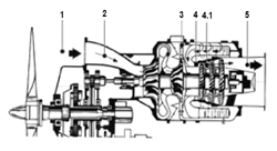
1 - Ambient (air surrounding the engine)
2 - Compressor Inlet (inlet to the first stage compressor)
3 - Compressor Discharge (area of highest pressure within the engine)
4 - Turbine Inlet (area of highest temperature within the turbine section)
4.1 - Interstage Turbine (inlet to the second stage turbine stator)
5 - Exhaust (turbine discharge)
Discuss this article in the forums...