preflighting the tpe331 engine

By Helmuth Eggeling
The TPE331 engine that powers all turboprop Twin Commanders has been around for decades, but the operating principles that guided its design�simplicity, power, fuel efficiency, and safety�are as relevant today as when the first production engine appeared more than 45 years ago. The following article, which is adapted from Honeywell�s TPE331 Pilot Tips booklet (available online at https://www.e-engines.honeywell.com/index.jsp; point to �Communications,� then �Pilot Information� then click on �Pilot Tips Book�) takes a look at preflight inspection procedures.
NORMAL OPS PROCEDURES CHECKLIST
Preflight Inspection
The importance of a thorough preflight inspection by a flight crewmember cannot be overemphasized. Remember, in some cases it will be necessary to use a stepladder to adequately examine the engine inlet area.
- Cleared/Deferred write-ups�checked
- GPU (if use is intended)--check operation
Caution: Consult the AFM/POH for the appropriate electric rating when using a GPU for engine starting or systems checks.
- Engine inlet/exhaust cover�removed
- Engine cowling�inspect security
- Oil level and filler cap�check level and security
Warning: Visually confirm a clear propeller before engaging the starter or before motoring the propeller.
Warning: Exercise extreme care when opening oil tank dipstick cap immediately following engine shutdown because hot oil can spill and cause injury.
- Oil/fuel filter bypass valves�check indicators
Redesigned bypass valves (if incorporated) provide a thermal lockout, preventing bypass indicator extension at oil temperature below about 38 degrees C.
Fuel filter bypass: Some installations have a pin or poppet that extends to indicate that the fuel filter bypass valve has opened. Other installations have pressure ports on the bypass valve, causing a cockpit light to illuminate whenever restricted fuel flow is encountered, indicating an impending filter bypass condition.
- Fuel drains�check as per AFM/POH
- Oil cooler air inlet�check. Should be clean, unobstructed, no evidence of leaks
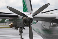
- Propeller blades�check (on the start locks)
- Propeller blades�condition
- Propeller hub/spinner�check
Caution: Damaged or blocked sensors can send erroneous signals to the FCU/SRL and can cause erratic engine operations.
- Engine inlet�check sensors.
The inlet should be clear and unobstructed.
Check inlet surface for discoloration (possibly due to excessive use of inlet heat during ground operation) and for evidence of residual oil. (Minor compressor seal leaks are typically a nuisance and do not normally affect the airworthiness of the engine. However, the leak should be written up and brought to the prompt attention of your maintenance department or service facility.)
The P2-T2 sensor (T2 only with Bendix FCU) should be checked for security and to assure that they are undamaged and clean.
- Tt2 Sensor (SRL/VRL)--check
If located in the inlet, the Tt2 sensor can be found opposite of the P2T2 sensor, in the oil cooler inlet or anywhere on the engine cowling, depending on the aircraft type.
The Tt2 sensor provides temperature-sensing information to the SRL controller on Dash 10 engines.
The sensor should be checked for general conditions and security.
- Engine inlet/1st stage�check compressor
- Propeller�rotate by hand
If an abnormal resistance is noted (for example, shaft bow; rotational freedom should be re-checked after about three minutes of additional cooling), hand rotation should be stopped at the point where the resistance is most obvious; representing 180 degrees displacement of the main rotating group (neutralizing the thermally caused imbalance as cooling continues). Note: Rotational resistance is unusual except for the initial few hours of operation following replacement of the inter-stage air seals.
Caution: Do not start the engine if the propeller is not free to rotate.
- OAT sensor�check
Note: Engine performance and operating characteristics are a function of OAT and PA. The OAT sensor may pick up reflected ground heat and thus may read a higher ambient temperature than the OAT reported from an official meterological observation source. The error will vary with sun position and type of ground surface.
- Exhaust nozzle�check
- Turbine blades: condition
- Aircraft orientation�into the wind
A headwind provides windmill power, ram inlet air, and a clear exhaust path.
Note: Except as noted in some AFMs and POHs, there are no wind restrictions for engine starts because maximum tailwind is a function of other start condition, e.g., start-bus voltage, residual turbine temperature and ambient conditions.
For additional information concerning TPE331 design and operation, please contact me at 602 231-2697, or send an e-mail message to [email protected].
Discuss this article in the forums...